Live rain fall monitoring via LoRaWAN
This text briefly describes a rain gauge setup which uses LoRaWAN to transmit rain fall events to an online database. The setup makes use of the high precision ONSET HOBO rain gauge. Instead of using the vendors data logger which requires manual at-device data transfers, a LoRaWAN compatible microcontroller sends data wirelessly.
LoRaWAN allows low bandwidth data transmissions over long ranges while requiring minimal power. While sensor nodes are individually managed, the gateways, receiving and forwarding data packets to an online database, can be maintained by institutions and are often free of charge. These properties make LoRaWAN a good replacement for other wireless sensor setups. The possible ranges are higher than ZigBee, federated gateways allow resource sharing and no service subscriptions like fore GSM apply.
Motivation
Using the ONSET HOBO rain gauge requires manual data transfers by using a short distance data transfer via a LED. This means every data extraction requires someone to visit the rain gauge with special equipment. If the station breaks or is stolen, all data since the last transfer is lost. Rain gauges may be deployed in mountains or inaccessible areas which makes data transfers more time consuming and less frequent.
Secondly the collected data might be highly delayed due to the collection style. If a special weather event happens, the data is only available after the next collection. In cases of heavy storms all data could be lost if the sensor node is flooded away.
Lastly, the data can not be used for alerts of e.g. flash floods, where a live stream of data is required to instantly recognize heavy rainfalls.
To lower the workload of maintaining rain gauges and allow live data processing, the on-device storage is replaced with a microcontroller capable to transmit recordings wirelessly.
Setup
The setup essentially uses an Arduino microcontroller and a rain gauge sensor, both described in the next two sections. For a waterproof outdoor setup, recharged via a solar panel, the following parts were used:
- Awclub Waterproof Junction Box
- AOSHIKE Mini Solar Panel
- MCIGICM Breadboard
- MakerFocus 3.7V JST1.25 Battery
- A 10k Ohms resistor
- Wire to connect
All parts combined cost including the Arduino microcontroller and excluding the rain gauge less than $35. The price of the rain gauges vary between $420 for a nONSET HOBO and $10 for a misol WH-SP-RG.
Rain gauge sensor
This setup uses the ONSET HOBO sensors, while possible to deploy other rain gauges to decrease the cost. Other vendors like misol offer rain gauges following the same mechanical principle. The misol WH-SP-RG cost a fraction of the ONSET HOBO and may offer sufficiently accurate results.
To be compatible with this setup a magnetic reed switch is required and both the volume to tip the seesaw and the size of the collection surface have to be known.
Arduino microcontroller
This section contains two sub-sections, covering the hardware and the software setup. A drill as well as a hot-glue gun are required plus minimal knowledge of the C programming language.
Hardware setup
For this setup an Arduino compatible Heltec AB02 development board is used. It allows quick prototyping, supports the official LoRaWAN C implementation and comes with a solar battery charger.
Other microcontroller are possible to use as long as they support LoRaWAN and can handle a single interrupt GPIO pin.
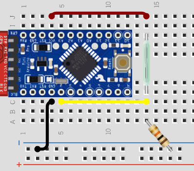
The reed switch is connected like other switches on an Arduino board. A 5V power source connects one side of the switch while the other side is connect to a GPIO pin and 10K Ohms resistor, which goes to ground (GND). The picture on the right shows a setup example. For a real deployment the green reed switch is replaced with a wire connecting the rain gauge.
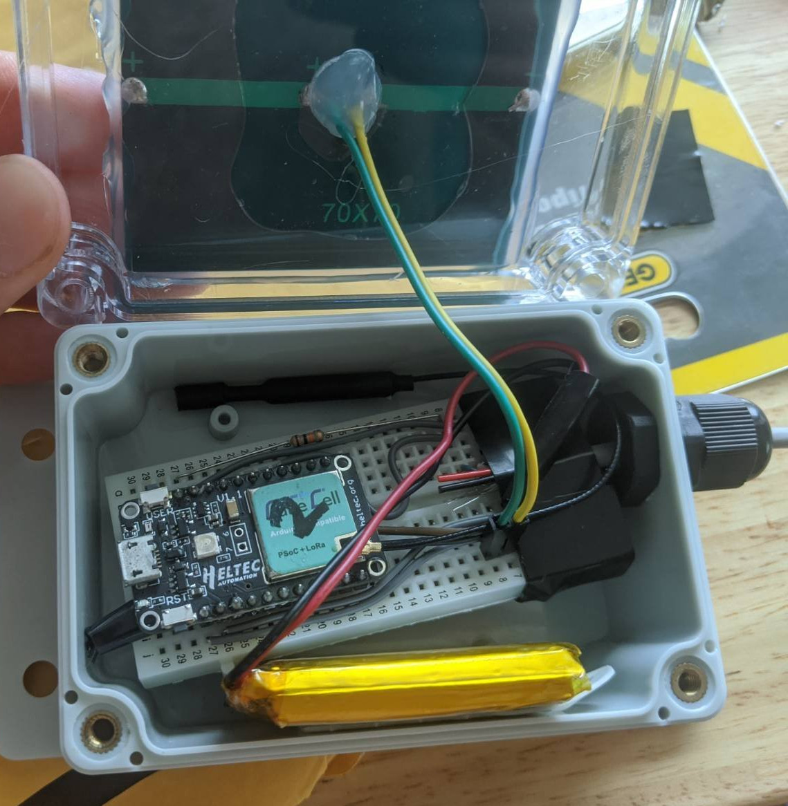
Below is an illustrative arrangement of the components. Both breadboard and battery can be glued to the case with two sided tape. For the solar panel a hole is drilled in the transparent lid which only needs to fit two wires. A glue-gun is used to seal the lid and solar panel again water.
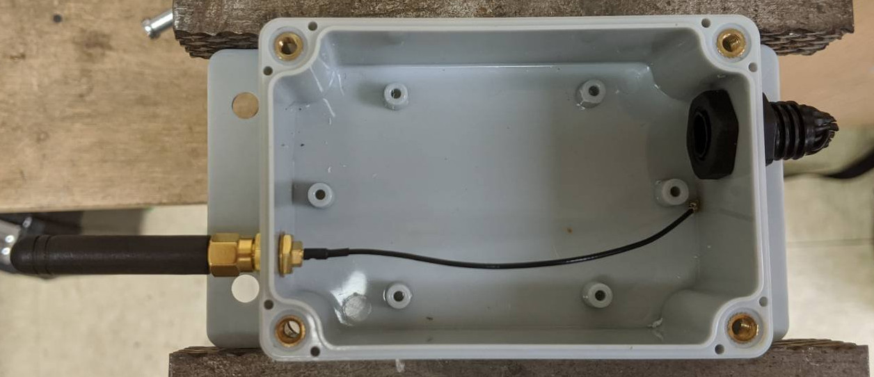
Below shows a possible arrangement of the external antenna and a PG7 cable gland to connect the external rain gauge.
Software setup
The full source code is available on GitHub with an additional provision script which is helpful when setting up multiple sensor nodes.
It is recommended to use Platformio to manage library dependencies and compilation, it is however possible to use any other Arduino development setup.
The code is mainly based on the official Heltec example code for LoRaWAN applications, with simple additions to read rain gauge events and send data via the CayenneLPP protocol.
As bandwidth is prestige in LoRaWAN the rain gauge does avoid sending null data,
meaning if it does not rain, no packets are send. On the other hand it is
important to know that the sensor is alive even over dry periods. For that the
sensor sends every BATTERY_SEND_INTERVAL minutes a heartbeat containing the
current battery voltage. With the current implementation the prepareTxFrame
function is called once a minute, allowing up to 60 measurements per hour.
A heartbeat is send every 30 minutes.
34 static void prepareTxFrame(uint8_t port)
35 {
36     // contains the LoRa frame
37     CayenneLPP lpp(LORAWAN_APP_DATA_MAX_SIZE);
38     // send battery status only every "BATTERY_SEND_INTERVAL" minutes
39     if (battery_send_counter <= 0) {
40         lpp.addVoltage(1, getBatteryVoltage() / 1000.0);
41         battery_send_counter = BATTERY_SEND_INTERVAL;
42     } else {
43         Serial.println("Skip adding batter volt");
44         battery_send_counter--;
45     }
46
47     if (tips > 0) {
48         Serial.printf("Tips = %i\n", tips);
49         lpp.addAnalogInput(1, mm_per_tip.number * tips);
50         tips = 0;
51     } else {
52         Serial.println("Skip adding rain fall");
53     }
54
55     appDataSize = lpp.getSize();
56     Serial.printf("appDataSize = %i\n", appDataSize);
57     lpp.getBuffer(), memcpy(appData, lpp.getBuffer(), appDataSize);
58 }
Below is an implementation of custom AT-commands, meaning commands send over
the serial console to the controller allowing modifications without re-flashing
the sensor node. The mmPerTip AT-command sets the mm reported per tip. This
value defaults to 0.01" or 0.254mm, however this depends on the rain gauge used.
61 bool checkUserAt(char* cmd, char* content)
62 {
63     // this command is used to set the seesaw size
64     if (strcmp(cmd, "mmPerTip") == 0) {
65         if (atof(content) != mm_per_tip.number) {
66             mm_per_tip.number = atof(content);
67             Serial.print("+OK Set mm per tip to ");
68             Serial.print(mm_per_tip.number, 4);
69             Serial.println("mm");
70             Serial.println();
71             FLASH_update(addr, mm_per_tip.bytes, sizeof(mm_per_tip.bytes));
72         } else {
73             Serial.println("+OK Same mm per tip as before");
74         }
75
76         return true;
77     }
78     return false;
79 }
Each tip of the rain gauge causes an interrupt function to run, adding to the total number of tips. After each send packet the number of tips is reset to zero. To avoid double counts caused by flickery GPIOs, a tip can only happen every 100ms. In practise the seesaw can not tip faster than 1Hz with the possible water flow.
81 // run on each interrupt aka tip of the seesaw
82 void interrupt_handler()
83 {
84     if (labs(millis() - last_switch) > 100) {
85         tips++;
86         last_switch = millis();
87     }
88 }
The code below prevents sending of null packages, it checks if the transmission frame is empty and if so, refrain from sending the packet.
133         if (appDataSize > 0) {
134             LoRaWAN.send();
135         } else {
136             Serial.println("Package is empty, don't send anything");
137         }
138         deviceState = DEVICE_STATE_CYCLE;
139         break;
Once flashed and provisioned the sensor nodes sends LoRaWAN packets. For this setup the free and community oriented LoRaWAN provider The Things Network was used. It is also possible to use other cloud providers supporting the LoRaWAN standard or hosting ones own backend, e.g. with ChripStack.
Live monitoring
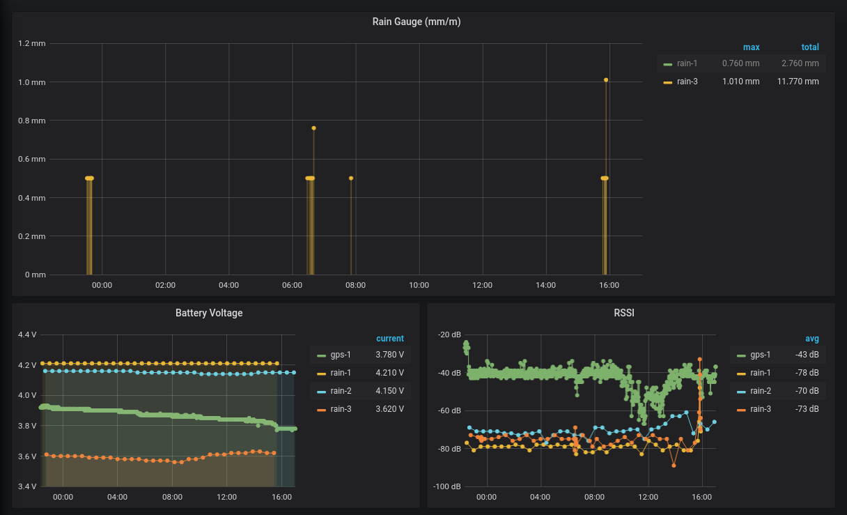
This post should not cover the details of the monitoring setup, in short a InfluxDB is fed via Telegraf and data is presented via Grafana. With that or similar setups it is then possible to monitor in real time rain fall over multiple location.
Below a simple Grafana dashboard showing the rain fall of the sensors rain-1
and rain-2, as well as battery voltages and RSSI.
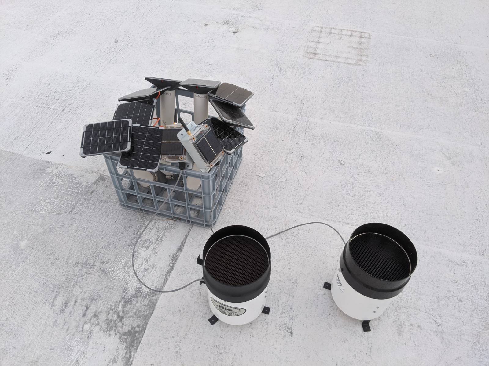
The setup itself is on the roof of a building and the next gateway in a 2.5 mile dinstance.
Conclusion
TBD